

Unit clearance c Unit dedendum fillet r f Face widths b 1, b 2 Unit worm gear correction x Worm size can be specified using the: worm diameter factor q helix direction γ pitch diameter.. 8964 ————————- 12 5665 ————————- 15 7086 3 ———————– 19.
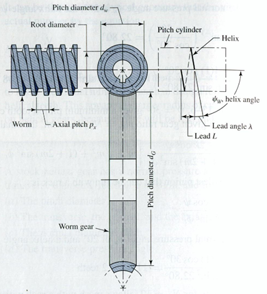
Steps of the Design CalculationThe axial pitch of the worm and the circular pitch of the gear must be same for a mating worm and gear.. D1 – Pitch Diameter of WormD2 – Pitch Diameter of GearC – Centre to Centre Distance between the Worm and the GearThis worm gear design tutorial will discuss up to the selection of the module and pitch and the calculation of the number of teeth, pitch circle diameter and centre to centre distance between the worm and gear.. Input Parameters Teeth type - common or spiral Gear ratio and tooth numbers Pressure angle (the angle of tool profile) α Module m (With ANSI - English units, enter tooth pitch p = π m) Unit addendum ha.. Now, let’s say we have the following design input:Speed of the Worm (N1) = 20 RPMSpeed of the Gear (N2) = 4 RPMAnd, we have to find out the Module (m), Pitch (P), Number of helix of Worm (T1), Number of teeth of Gear (T2), Pitch circle diameter of Worm (D1), Pitch circle diameter of Gear (D2), Centre to centre distance(C).
worm gear design calculation
worm gear design calculation, worm gear design calculation pdf, worm gear design calculation excel, worm gear design calculation online, how to design worm gear, how to measure worm gear, how to calculate gear ratio for worm gear, worm gear design formula, worm gear box design calculator Download Magicard Rio Pro Drivers
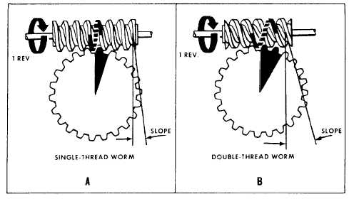
Worm Gearing 50 Lead Angle Worm threads are Perature and the details of the gear mesh design. Download Pdf Reader Mac Free
worm gear design calculation excel
how to design worm gear
Look at the picture below:Where,Calculations for worm gears are the same as for.. We will use the AGMA formulae for doing the calculations Design calculations of the other aspects of the worm gear will be discussed in a subsequent part of the tutorial.. Worm gear pdf - Free download as PDF File ( pdf), Text File ( txt) or read Of a worm gear is related to its circular pitch and number of teeth Z by the formula.. Worm and WormGear Design Equations and Calculator Gears Engineering and Design Equations for American Standard Fine Pitch Worms and Wormgears Per.. 238 Use the following gear design equation:N1/N2 = T2/T1And, we will get:T2 = 5 * T1……………….. 7928 ————————– 25 13310 ————————- 31 41612 5 ———————– 39.. 238Worm Gear Calculation2 5 ———————- 7 8543 15 ——————— 9. 518b7cbc7d
0